Aluminum Brazed Joints: Specify Clearance and Filler Supply Together
Connect joint clearance, clad material and added filler placement in the drawing review before qualifying an aluminum brazing assembly.
China Thermic Editorial Team
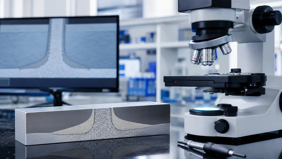
Joint clearance and filler supply should be specified together when designing an aluminum brazed assembly. A clearance recommendation for externally supplied filler cannot automatically be transferred to a clad tube-to-header joint. Identify how filler reaches each joint before finalizing tolerances.
MAP THE FILLER SOURCE
For every critical joint, record whether filler is supplied by cladding, a preform, wire or an approved metallized paste. Identify the material specification and placement requirement on the controlled drawing or assembly instruction. Distinguish the flux requirement from the filler-metal requirement so an operator is not left to infer what an application step supplies.
The NOCOLOK Encyclopedia distinguishes non-clad joints with externally fed filler from clad joints where the cladding contributes to the joint arrangement. This is a process-specific distinction, not a reason to copy a nominal gap without checking the complete material and assembly design.
REVIEW THE TOLERANCE CHAIN
Consider the dimensions that establish the assembled joint, including formed features and locating surfaces. Ask which measurement demonstrates that production parts meet the intended condition. A drawing can specify a local gap while the chosen inspection method measures only an unrelated overall dimension.
Record the preparation and assembly sequence used to obtain the joint condition. If a forming or insertion operation changes, examine whether the previous fit-up evidence still represents the revised process. Make any permitted adjustment visible in the instruction rather than relying on an experienced operator's informal correction.
VERIFY THE JOINT AFTER BRAZING
Select representative locations for joint examination and agree on the required evidence before running the trial. Link dimensional checks, joint sections and applicable functional tests to the actual material and filler arrangement. Preserve photographs of the unbrazed assembly alongside the completed inspection so design decisions remain traceable.
Do not use an attractive external fillet as the only basis for accepting hidden joints. The validation plan should address the characteristics required by the product, including regions that cannot be judged from a surface photograph.
FREQUENT QUESTION: WILL ADDING MORE FILLER SOLVE AN INCONSISTENT JOINT?
Not necessarily. First review the fit-up, filler location, material combination and qualified process conditions. Any filler change should be evaluated against the complete joint requirements.
DECISION CHECKLIST
Confirm the filler source, clearance basis, tolerance chain, assembly method, inspection locations and validation evidence before releasing the joint design.
SOURCE
Solvay NOCOLOK Encyclopedia, joint-clearance guidance for clad and non-clad components. https://www.aluminium-brazing.com/sponsor/nocolok/Files/PDFs/NOCOLOK-Encyclopedia-2013.pdf